About this deal
Soft start function (reduces current ripple and spikes during start-up, by limiting the initial current flow). This circuit is similar to the above except output voltage in the circuit can be adjusted. As I already mentioned that output voltage is set by means of Voltage fed into the FB pin of MT3608. Here I have replaced the resistor R1 with Potentiometer PR1. As the resistance of POT changes the voltage in to the FB pin changes which in turn will change the output voltage accordingly. You are using a 22µH inductor, which is at the high end of what the datasheet says. I started my design by copy/paste of an existing easyEda project which was with a 4.7µH… what is the difference between the 2 choices? what would you recomend I use for my design? Would you have a part number to suggest? I have shared my project on easyEda at: https://easyeda.com/editor#project_id=9220fa26c27845ae8d1bbd93b3a543d9 fans sould be find you will need a splitopr thow(just dont do more then 3) ya it will make your argb 5v dum like 12v.
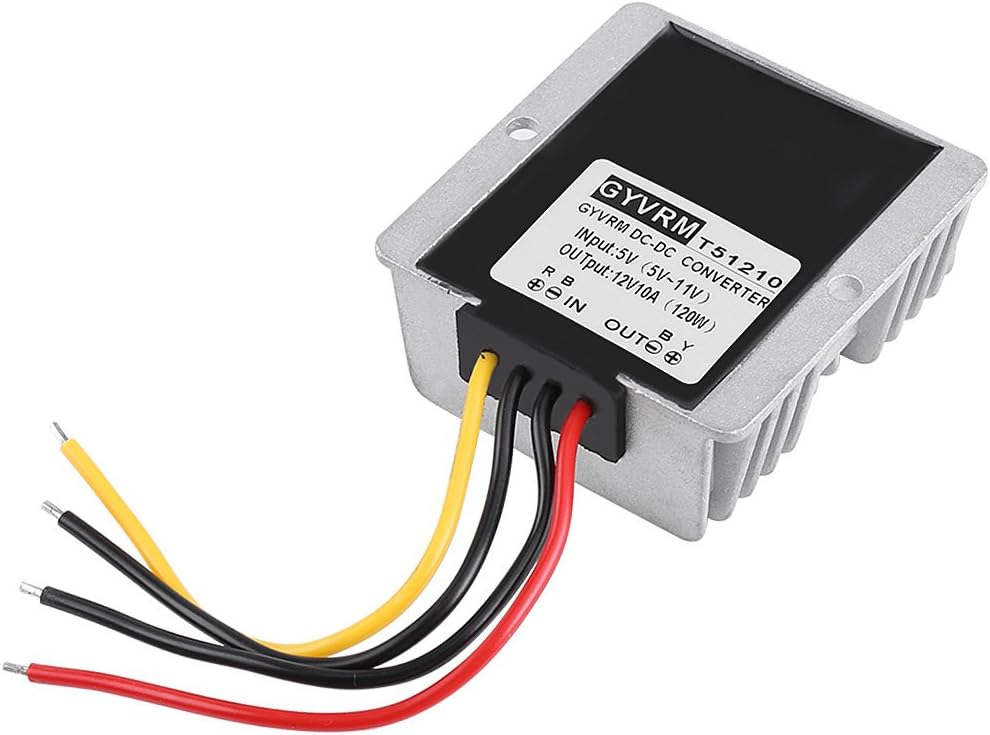
Converter, 5V To 12V USB Step Up Voltage Qutaway Step Up Converter, 5V To 12V USB Step Up Voltage
If you want your 5V ARGB devices to act like 5V ARGB devices (multiple colors at the same time) you will need an ARGB signal coming from somewhere. Many controllers can get their ARGB signals from USB 2.0 headers and third party software instead of a dedicated header and motherboard software (Such as Corsair or NZXT, but I dont know of any brands that work with standard ARGB equipment off the top of my head.) It depends on the input voltage and current, the amount of the maximum stable output current is produced. These DC-DC boost converter modules operate at the frequency ≥1.2MHz, the typical efficiency is 93% subjected to the withdrawn load current. After the MOSFET is turned off, the magnetic field of the Inductor turns in to voltage spike and it goes through the Schottky diode. Hence this voltage spike will be exhibited as output in the circuit. As there is a capacitor in the output, it charges in every cycle of oscillation and keeps the voltage constant. In this voltage booster circuit components are used to boost 5v to 12v. Above all for MT3608 to start working, the EN pin should be tied to high. If you want to turn on and off the output with an external circuit you can use this pin. This circuit is capable of delivering 2A current to the Load. ADJUSTABLE OUTPUT VOLTAGE: With the voltage boost converter module with IC Lm2577-ADJ, you can draw 12V @800mA stable DC voltage output at a wide range of input voltage levels from 3V to 40V. The LM2577 is designed with an 3.0A NPN switch, which is also equipped with a thermal and current limiting protection circuit.Really my question is would I need to put another diode at of the end of each V+ booster circuit before the parallel connection or will the circuit work without this? Below schematic is implemented using readily available Lm2577-ADJboost converter IC having adjustable output feature: Depending on what you plan to power with that, you might consider regulation and electrical isolation. This design has a 22µF “output” capacitor. But I already have a 100µF capacitor as an “entry” to the A4988 stepper. PCB space is VERY limited for me. Can I just use the 100µF and drop the 22?
LT1173 Datasheet and Product Info | Analog Devices
A hub only adds more headers if you have a motherboard with 1 3-pin 5v header. My motherboard has 0 3-pin 5v headers.The output source impedances are typically 150Ω, providing useful output currents up to 10mA. The low quiescent current and high efficiency make this device suitable for a variety of applications that need both positive and negative voltages generated from a single supply. In this post we will be avoiding using the old school method and only focus on boost converters with simple ICs. Earlier methods or you can say older methods used transistors as a switching device externally and lots of components were required to implement it making it complex. That is the reason to go with ICs and modules. Also it will save a lot of time to center your attention towards the actual functioning of the project rather than the power supply.
 Great Deal